This article briefly touches on U.S. 3.5 GHz Citizens Broadband Radio Service (CBRS) and 3.7 GHz C-Band, how CBRS users are managed to minimize spectrum conflicts, and options for mitigating interference. Test equipment configurations include spectrum analysis (SA) with and without time-gating, real-time spectrum analysis (RTSA) using time markers, and the use of external bandpass filters. The overall goal of this article is to assist my customers with interference mitigation in these bands. Constructive feedback is always appreciated and welcome.
CBRS and C-Band use time division duplexing (TDD), where the downlink (DL) and uplink (UL) use the same frequencies in different time slots. These bands will not generate passive intermodulation (PIM) because the DL is inactive when the UL is active. However, PIM and/or harmonics from lower frequency division duplexing (FDD) LTE bands may impact CBRS and/or C-Band, when these systems are co-located into existing cell sites and antenna skew exists.
For CBRS, the FCC developed the following tiers to minimize spectrum conflicts:
- Tier 1 – Incumbent Access users have the highest priority. This includes authorized federal users (3.55 to 3.7 GHz), fixed satellite service earth stations (3.60 to 3.65 GHz), and grandfathered wireless broadband licensees (3.65 to 3.70 GHz).
- Tier 2 – Priority Access users are also referred to as Priority Access Licenses or PALs (3.55 to 3.65 GHz).
- Tier 3 – General Authorized Access (GAA) is open and users can operate between 3.55 to 3.70 GHz as long as they do not interfere with Tiers 1 and 2.
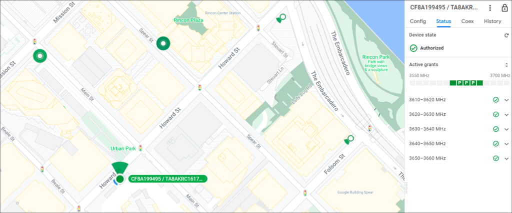
CBRS spectrum is managed by FCC approved Spectrum Access Systems (SAS) administrators, which may incorporate Environmental Sensing Capability (ESC) sensors. ESC sensors detect Tier-1 activity and then sends this information to the SASs to shut down potential spectrum conflicts. SASs also manage Tier 2 (PAL) spectrum conflicts with Tier 3 (GAA) users. One example of SAS is shown below.
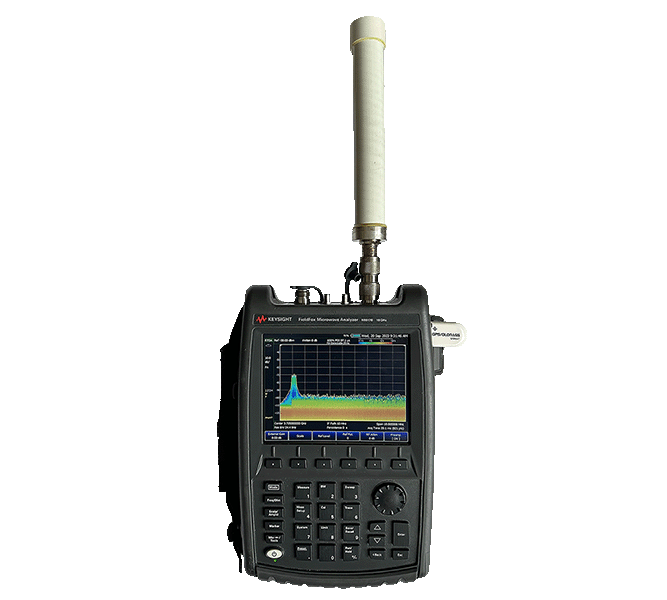
A bandpass filter is still recommended, as with FDD mitigation; however, as long as your spectrum analyzer is not under compression or saturation, there should not be a need for a filter. Having said that, proper filter bandwidth tailored to the desired input signals can greatly reduce some, if not most of the un-wanted mixing products generated by the spectrum analyzer (SA) system. In addition, the use of an external filter helps to prevent accidental input damage to your test unit and is almost always required for low power (<-110 dBm) noise issues. One option for an external bandpass filter for CBRS and C-Band is 3.55 GHz to 3.98 GHz. The setup below is shown without the use of a bandpass filter.
External test equipment requirements and setup will be governed by the band under test, the bandwidth of the interference, whether it is intermittent or constant, the power level of the interference, and the capabilities of your test equipment. The following illustrates some options:
- CBRS DL Only Configurations: The easiest option is to monitor the DL with your spectrum analyzer (or equivalent) with the preamplifier off and internal attenuation set to an appropriate level to protect the frontend. This configuration can be used for non-noise related issues where the interference power level is high enough to get above the test unit’s noise level. A 30 dB external step attenuation is recommended for further protection and to quickly test for input saturation. An external bandpass filter may not be required. A real-time spectrum analyzer (RTSA) or equivalent or a time-gating function is more than likely not required.
- CBRS UL and C-Band Configurations: It may be possible to use the setup mentioned above for DL only issues; however, in most cases, one of the following will be required:
- Spectrum Analyzer or Equivalent (No Time-Gating): SA’s preamplifier is set to “On”, internal attenuation is set to 0 dB, and an external bandpass filter is highly recommended. This setup is very prone to input saturation when an external bandpass filter is not used and may make it difficult to see UL interference. Recommend setting trace #2 to maximum hold if interference source is intermittent.
- Real-Time Spectrum Analyzer or Equivalent: This is by far one of the most effective solutions and does not require knowledge of radio frames and their configurations. This configuration works with all type of interference. An external bandpass filter will more than likely be required for noise issues. The example below illustrates the use of a spectrogram with time markers. Notice how the spectrum alternates between the UL and DL; therefore, both UL and DL issues can be mitigated.

Real-Time Spectrum Analyzer (RTSA) with Time Markers
(GPS Coordinates, Elevation, & SN Removed for Privacy)
- Spectrum Analyzer (Time Gating): This is by far the most complex setup where knowledge of radio frames and their configurations are required to setup SA. These settings could be given to a user; however, there is still the concern of the SA’s sweep speed. The example below shows time-gating for the C-band. The top screen is the uplink (frequency domain) and the bottom is the time domain. As with the RTSA setup above, an external bandpass filter will more than likely be required for noise issues.

Spectrum Analysis with Time Gating
(GPS Coordinates, Elevation, & SN Removed for Privacy)
Ultimately, TDD interference should prove to be much easier to resolve than PIM in the lower FDD LTE bands. This is especially true for CBRS DL only configurations. It is important to be capable of thinking outside the box when mitigating interference in these bands.
Go to bryantsolutions.com for more information regarding our RF engineering, field support, and training services.